Voltage drop across a resistance
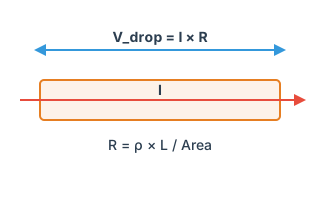
Work out the voltage drop from a resistance and a current. By Ohm's law, current through a resistance produces a drop across it.
SI prefixes accepted (4k7 / 1M / 10m / 220). Upper-case M = mega, lower-case m = milli
Derived values
- Resistor dissipation
- 1 mW
- I² × R
- Recommended power rating
- 2 mW
- 50% derating
A 1/16W (1005 / 0402) chip resistor is enough.
History
Formula
With current in mA: V = R × I[mA] × 0.001
Design notes
Ohm's law, V = IR, is the foundation of circuit design. Current limiting resistors, wiring resistance, connector contact resistance — knowing the drop matters in all of them.
Where it comes up:
• Checking the drop along a long supply cable (say 2 A down a 1 m run)
• Checking the loss along a PCB trace carrying a heavy current
• Loss across the contact resistance of a connector
Rules of thumb for what is acceptable: ±5% on digital rails (0.25 V on a 5 V rail), and whatever your accuracy demands on analogue ones.
When you need this
The most basic check there is: the drop across a series resistance. Useful for damping resistors, current-sense shunts, series elements in a supply rail, and pull-ups — anywhere you need to know what inserting a resistor costs you in volts.
Where it comes up
- Current-sense shunts. A larger sense voltage improves accuracy but takes voltage away from the load and dissipates more. 100mΩ at 1A is 100mV of drop and 100mW of loss.
- Damping resistors. A 33Ω series resistor into a CMOS input passes almost no DC, so there is no static drop. It acts only on transient current.
- Pull-up resistors. An I²C bus with 4.7kΩ sinks 3.3V / 4.7kΩ ≈ 0.7mA in the low state. Check that this satisfies the device's Vol specification.
- Series filtering on a rail. Ferrite beads or resistors fitted for noise cost you their DC resistance. Bead DC resistance ranges from tens of milliohms to several ohms.
Related calculators
For the drop along a PCB trace, Trace resistance and parasitics is a better fit — it derives resistance from width, length and copper weight and reports heating at the same time.
To create a voltage by division, use Resistor divider, which also reports worst-case values including tolerance.
Frequently asked questions
What about the power dissipated in the resistor?
I want the drop along a trace.
Standards and references
- IEC 60115-1 — Generic specification for fixed resistors.
Last updated: 2026-08-29