Capacitor code
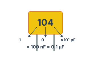
Work out the capacitance from the 3-digit code printed on a chip capacitor. Example: 104 = 0.1 µF
History
Formula
Example: 104 → 10 × 10⁴ pF = 100,000 pF = 0.1 µF
Design notes
Chip capacitors carry their value as three digits. The first two are the significant figures and the last one is the multiplier — the power of ten.
Codes you will see often:
• 104 → 0.1 µF (the usual decoupling value)
• 103 → 10 nF
• 472 → 4.7 nF
• 220 → 22 pF (RF work)
Handy for identifying an unmarked part in stock, or checking a reel against the BOM before a build.
When you need this
For reading parts off an assembled board, or for turning a three-digit code from a schematic or BOM into a real capacitance. Repair, failure analysis and incoming inspection all involve reconciling parts against paperwork.
Reading the three-digit code
The first two digits are the significant figures and the third is the number of zeros. The unit is pF.
"104" is 10 followed by four zeros: 100000pF = 100nF = 0.1µF. "223" is 22 followed by three zeros: 22000pF = 22nF. It becomes automatic with practice, but the step to µF is where mistakes happen.
Common values
| Code | pF | nF | µF | Typical use |
|---|---|---|---|---|
| 101 | 100 pF | 0.1 nF | 0.0001 µF | RF bypass |
| 102 | 1,000 pF | 1 nF | 0.001 µF | Filtering |
| 103 | 10,000 pF | 10 nF | 0.01 µF | Decoupling |
| 104 | 100,000 pF | 100 nF | 0.1 µF | The standard decoupling value |
| 105 | 1,000,000 pF | 1,000 nF | 1 µF | Bulk supply |
| 106 | 10,000,000 pF | 10,000 nF | 10 µF | Bulk supply |
| 224 | 220,000 pF | 220 nF | 0.22 µF | Intermediate value |
| 475 | 4,700,000 pF | 4,700 nF | 4.7 µF | Bulk supply |
Other markings
- Codes containing "R". "4R7" is 4.7pF, with R marking the decimal point. Used below 10pF.
- One or two bare digits. "47" means 47pF. Distinguish from three-digit codes by context.
- Tolerance letters. A trailing letter gives tolerance: J = ±5%, K = ±10%, M = ±20%, F = ±1%.
- Temperature characteristic codes. C0G / NP0 (very stable) versus X7R / X5R (high permittivity, larger value but varies with voltage and temperature). This distinction is sometimes more important than the value itself.
Chip capacitors carry no marking. You cannot read the value off the board — you need the schematic or BOM. Measuring in circuit is also unreliable because surrounding components affect the reading.
Frequently asked questions
Why are chip capacitors unmarked?
Are "104" and "0.1µF" the same?
When do I use C0G versus X7R?
Are there four-digit codes?
Standards and references
- EIA-198 — Temperature characteristic codes for capacitors (C0G / X7R and others).
- IEC 60062 — Marking codes for resistors and capacitors.
- IEC 60384-1 — Generic specification for fixed capacitors.
Last updated: 2026-08-29