Resistor code
Work out the resistance from the 3-digit code printed on a chip resistor. Example: 103 = 10 kΩ
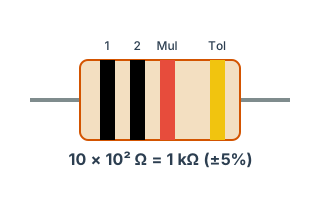
History
Formula
Example: 103 → 10 × 10³ Ω = 10 kΩ
Design notes
Chip resistors are marked with a three-digit code (four digits on precision parts). Even when the print on a small chip is hard to read, the code tells you the value straight away.
Codes you will see often:
• 103 → 10 kΩ (dividers and pull-ups)
• 472 → 4.7 kΩ (LED current limiting)
• 331 → 330 Ω
• 000 → 0 Ω (a jumper)
When you need this
For reading the marking on a chip resistor, or turning a three-digit code into a resistance. Unlike capacitors, resistors are marked, so they are one of the few parts you can identify from the board itself.
Reading the three-digit code
The first two digits are the significant figures and the third is the number of zeros. The unit is Ω.
"102" is 10 followed by two zeros: 1,000Ω = 1kΩ. "472" is 47 followed by two zeros: 4,700Ω = 4.7kΩ. The rule matches capacitors; only the base unit is Ω rather than pF.
Common values
| Code | Resistance | Typical use |
|---|---|---|
| 100 | 10 Ω | Damping, supply filtering |
| 220 | 22 Ω | Standard damping value |
| 330 | 33 Ω | Standard damping value |
| 101 | 100 Ω | General purpose |
| 221 | 220 Ω | LED current limiting |
| 102 | 1 kΩ | General purpose, pull-up |
| 472 | 4.7 kΩ | The standard I²C pull-up |
| 103 | 10 kΩ | The standard pull-up/pull-down |
| 104 | 100 kΩ | Weak pull-up |
| 105 | 1 MΩ | Bleed paths, high impedance |
Other markings
- Codes containing "R". "4R7" is 4.7Ω and "R47" is 0.47Ω, with R as the decimal point. Common on current-sense resistors.
- Four-digit codes (±1% parts). Three significant figures plus a zero count. "4701" is 470 followed by one zero: 4,700Ω = 4.7kΩ. Used for E96 values.
- EIA-96 codes. Parts 0603 and smaller use three-character codes such as "01A": two digits index the E96 series and the letter is the multiplier. You need a lookup table.
- "000" or "0". A zero-ohm jumper, used to configure the board through the layout.
Know the E series
Resistance values are not continuous; they come from the E series. E24 (24 values per decade, for ±5%) and E96 (96 values, for ±1%) are the common ones.
You cannot order the ideal value your calculation produced, so you must re-check the design with the E-series value you will actually buy. Rounding to E24 introduces up to about 2% error.
E24: 10, 11, 12, 13, 15, 16, 18, 20, 22, 24, 27, 30, 33, 36, 39, 43, 47, 51, 56, 62, 68, 75, 82, 91 — each multiplied by a power of ten.
Frequently asked questions
Is "103" 103Ω?
What are zero-ohm resistors for?
How do I read colour bands?
Why such odd numbers in E24?
Standards and references
- IEC 60062 — Marking codes for resistors and capacitors.
- IEC 60063 — Preferred number series (E6 / E12 / E24 / E96).
- IEC 60115-1 — Generic specification for fixed resistors.
Last updated: 2026-08-29