Convert mm to mil
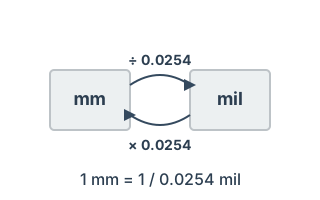
Convert millimetres to mils. 1 mil = 1/1000 inch = 0.0254 mm.
History
Formula
Design notes
In printed circuit board design, trace widths and via diameters are often specified in mils (1 mil = 1/1000 inch). US EDA tools and component datasheets in particular tend to use mil throughout.
The conversion comes up whenever you write fabrication notes for the board house or check a Gerber file against a specification given in the other unit.
When you need this
For checking that traces you drew in millimetres satisfy the fabricator's minimums, which are quoted in mils. Typically used to sanity-check a layout before running the full design rule check.
Why PCBs are dimensioned in mils
Printed circuit boards developed in the United States, so the dimensional system is inch-derived. A mil is 1/1000 inch, and much of the field is still specified that way: component pitches (100mil for DIP and pin headers), board thickness (62mil = 1.6mm), and minimum feature specifications.
Design work outside the US is normally done in millimetres, so the manufacturing specification and the design data are in different unit systems as a matter of course. Check both before releasing to fabrication.
Values used in board design
| mil | mm | What it means on a board |
|---|---|---|
| 3 mil | 0.076 mm | Minimum width/space on dense boards (premium) |
| 4 mil | 0.102 mm | Practical floor for high-density work |
| 5 mil | 0.127 mm | Standard minimum width/space |
| 6 mil | 0.152 mm | Comfortably within cheap fabrication |
| 8 mil | 0.203 mm | Relaxed design |
| 10 mil | 0.254 mm | Ordinary signal trace |
| 20 mil | 0.508 mm | Light power trace |
| 40 mil | 1.016 mm | Power trace |
| 62 mil | 1.575 mm | Standard 1.6mm board thickness |
Fabrication specifications are usually written in mils while the CAD work is in millimetres. Remembering just 5 mil = 0.127mm and 10 mil = 0.254mm covers most situations mentally.
Common mistakes
- Confusing mil and mm and designing something 25.4 times too big. It sounds absurd, but it happens with imported component libraries. Always eyeball footprint outlines for plausibility.
- Assuming "mil" is short for millimetre. Documents from different regions use the term differently. Judge from the magnitude of the number.
- Rounding through a manufacturing limit. A 0.1mm trace is 3.94mil, which just misses a 4mil minimum. At the boundary, check before rounding.
Frequently asked questions
Are mil and thou the same?
What minimum trace width should I design to?
What is 100mil pitch in millimetres?
Standards and references
- IPC-2221B — Generic PCB design standard; conductor width and spacing.
- IPC-2615 — Board dimensions and tolerancing conventions.
Last updated: 2026-08-29